driving-lane-departure-warning
Built a real-time lane departure warning system with a monocular camera, using OpenCV.
Lane Departure Warning System for Autonomous Driving
Objective
A demo of Lane Departure Warning System: a monocular camera is used for detecting current lane, tracking the vehicle position and estimating the front road status.
Video demo (Click to see the full video)
Code & Files
1. My project includes the following files
(Note: the hyperlinks only works if you are on the homepage of this GitHub reop, and if you are viewing it in “github.io” you can be redirected by clicking the View the Project on GitHub on the top)
- calibration.py contains the script to calibrate camera and save the calibration results
- main.py is the main code for 2 demos
- lane.py contains the lane class
- camera_cal folder contains the images used for camera calibration and calibration results
- examples folder contains the sample images and videos
- environment-gpu.yml environment file with GPU
- README.md summarizing the results
2. Dependencies & my environment
Anaconda is used for managing my dependencies.
- OpenCV3, Python3.5
- you can use provided environment file with GPU to install the dependencies.
- OS: Ubuntu 16.04 (should work on other platform too)
3. How to run the code
If you want to run the demo, you can simply run:
python main.py
If you want to use the code to calibration your own camera and test the video, save the image into camera_cal and calibrate them with:
python calibration.py
4. Release History
- 0.1.2
- Update the README.md
- Date 19 April 2017
- 0.1.1
- Edit the visulization flag in lane.py
- Date 3 March 2017
- 0.1.0
- The first proper release
- Date 3 March 2017
Steps
1. Camera calibration
- Gather a set of chessboard images with camera
- Compute the camera calibration matrix and distortion coefficients with given a set images.
- Apply a distortion correction to raw images.
2. Lane detection / tracking
- Use color transforms, gradients, etc., to create a thresholded binary image.
- Apply a perspective transform to rectify binary image (“birds-eye view”).
- Detect / track lane pixels and fit to find the lane boundary.
3. Lane status anlysis
- Determine the curvature of the lane
- Compute the vehicle position with respect to center.
4. Lane augmentation
- Warp the detected lane boundaries back onto the original image.
- Print the road status into image
Camera Calibration
Compute the camera matrix and distortion coefficients
The code for this step is contained calibration.py. It start by preparing “object points”, which will be the (x, y, z) coordinates of the chessboard corners in the world. Here I am assuming the chessboard is fixed on the (x, y) plane at z=0, such that the object points are the same for each calibration image. Thus, objp is just a replicated array of coordinates, and objpoints will be appended with a copy of it every time I successfully detect all chessboard corners in a test image. imgpoints will be appended with the (x, y) pixel position of each of the corners in the image plane with each successful chessboard detection.
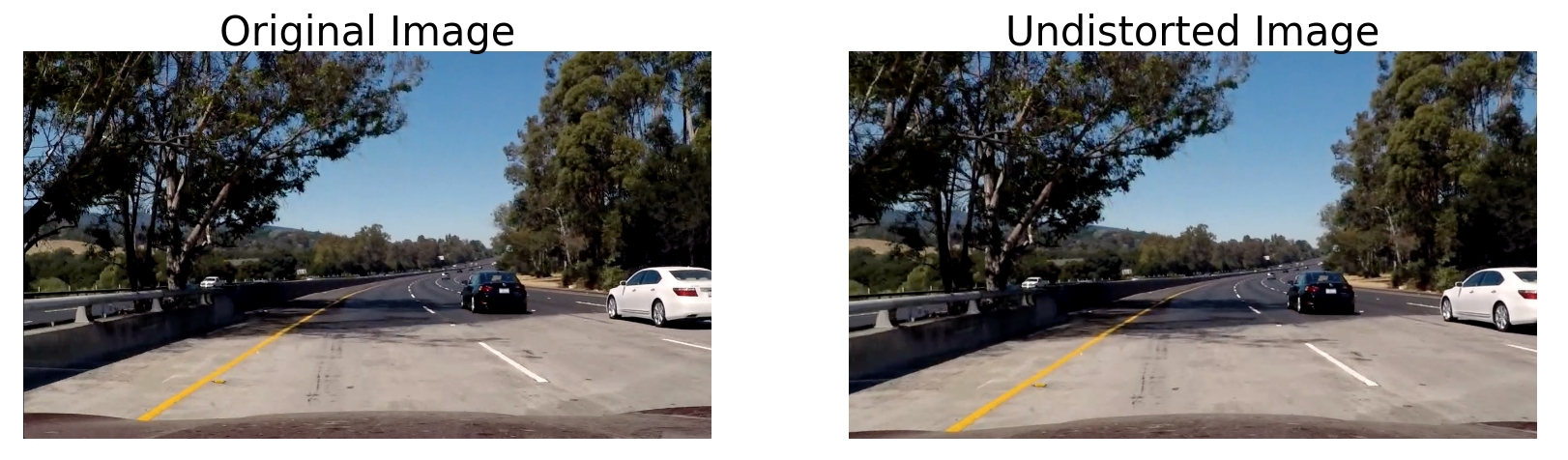
I then used the output objpoints and imgpoints to compute the camera calibration and distortion coefficients using the cv2.calibrateCamera() function. I applied this distortion correction to the test image using the cv2.undistort() function and obtained this result:

Pipeline to process image and video
Function process_frame() in lane.py contains every step described below.
1. Apply the distortion correction
In this step, cv2.undistort is used with the previous calibration results (see lane.py line 580). One of example for test images is as follows:
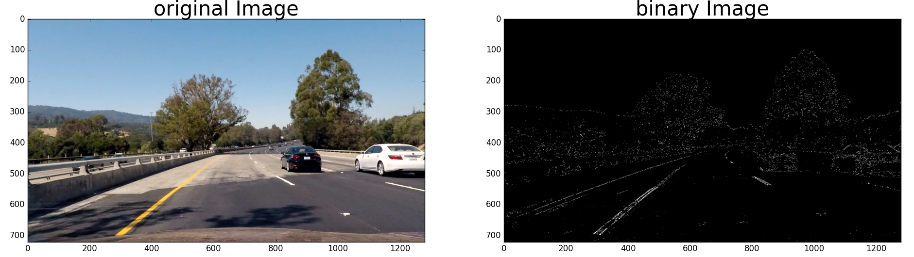
2. Use color and gradients filters to get a binary image
I used a combination of color and gradient (thresholds to generate a binary image (see function find_edges in lane.py line 187).
The image is firstly converted to HLS space, and I use the S channel to filter the image, by which is more robust to locate yellow and white lanes even under different lighting conditions.
Then a sobel filter (along x direction) and gradient direction filter is used to filter out most of the horizontal lines. Finally, to handle the cases where more than two candidate lanes are found,
I assgin the twice the weights to the S channel filter than the gradient filter. As a result, the yellow lane should be more visible than the edge of the road. Here’s an example of my output for this step:
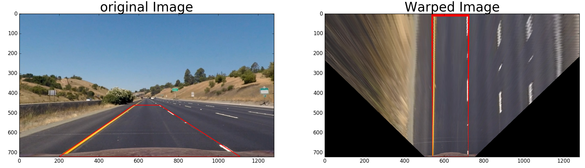
3. Use perspective transform to see the image in bird-view
The code for my perspective transform includes a function called warper() (in lane.py line 214). Firstly, I choose a
straight line driving image, and select 4 source points which form a trapezoidal along two lane lines, then I defined another 4 destination points,
so that I could get a perspective transform with cv2.getPerspectiveTransform function (see the two images below). The hardcoded source points and destination points are
listed as follows.
This resulted in the following source and destination points:
| Source | Destination |
|---|---|
| 194, 719 | 290, 719 |
| 1117, 719 | 990, 719 |
| 705, 461 | 990, 0 |
| 575, 461 | 290, 0 |
I verified that my perspective transform was working as expected by drawing the src and dst points onto a test image and its warped counterpart to verify that the lines appear parallel in the warped image.
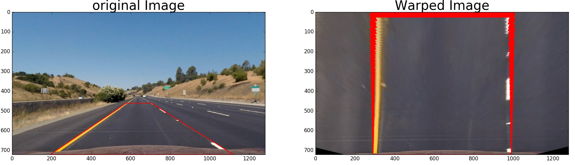
As we could probably noticed that the image are not in the right aspect ratio (flattened lanes), but it will have no effect on the final augmented image if we use the right inverse transform to warp the image back.
If we want to see the image in a more right scale, we could also select the destination points according to the right ratio of lane width and length in the trapezoidal. One example could be as follows:
4. Identify lane-line pixels and fit their positions with a polynomial
After applying calibration, thresholding, and a perspective transform to a road image, we should have a binary image where the lane lines stand out clearly.
However, we still need to decide explicitly which pixels are part of the lines and which belong to the left line and which belong to the right line.

For single image
If the input is single image or first frame of the video, a function named detector (line 548 in lane.py) is used. It processes the image as follows
-
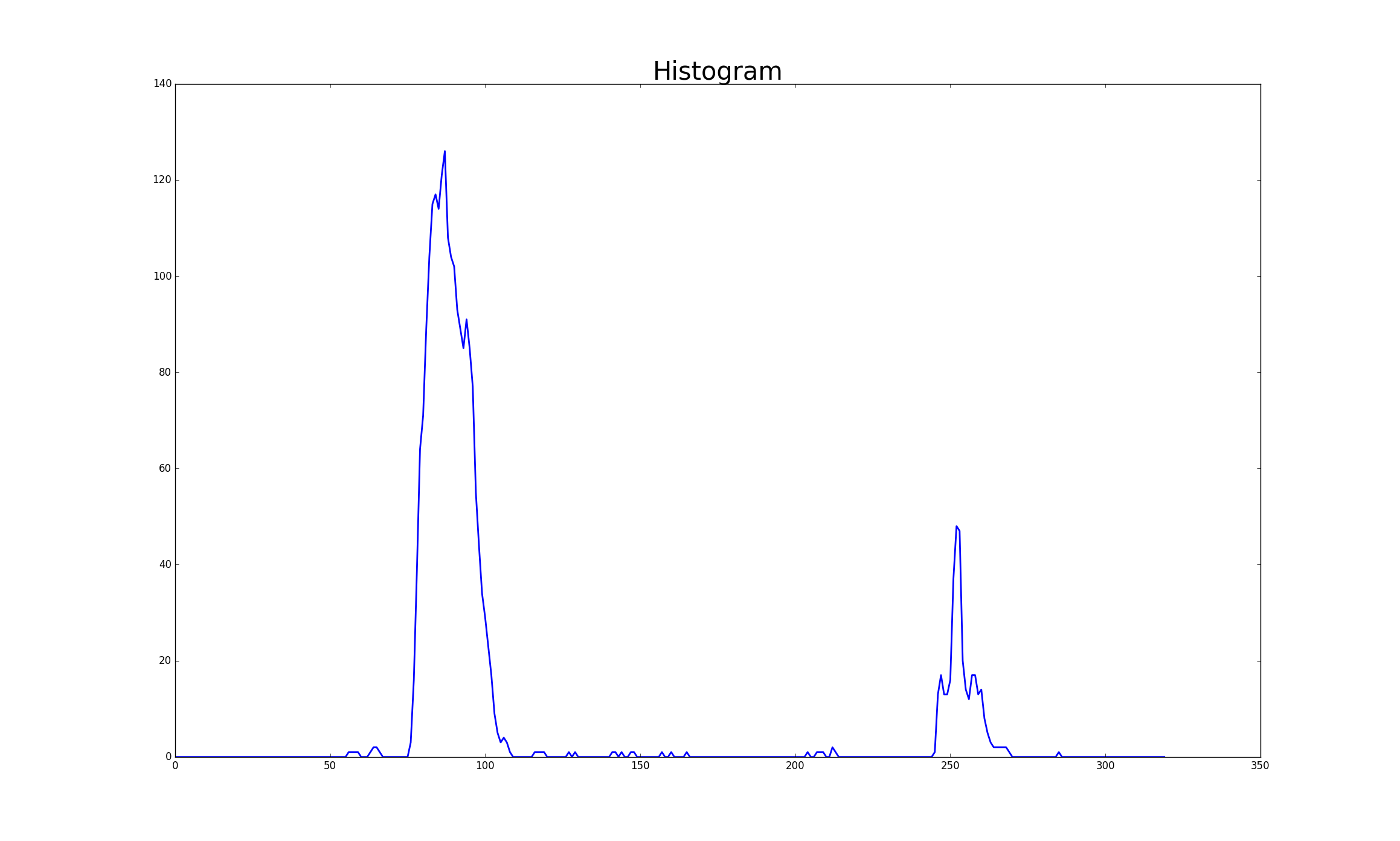
I first take a histogram along all the columns in the lower half of the image. The two most prominent peaks in this histogram will be good indicators of the x-position of the base of the lane lines. I can use that as a starting point for where to search for the lines. as a reuslt I will get similar figure as follows:
-
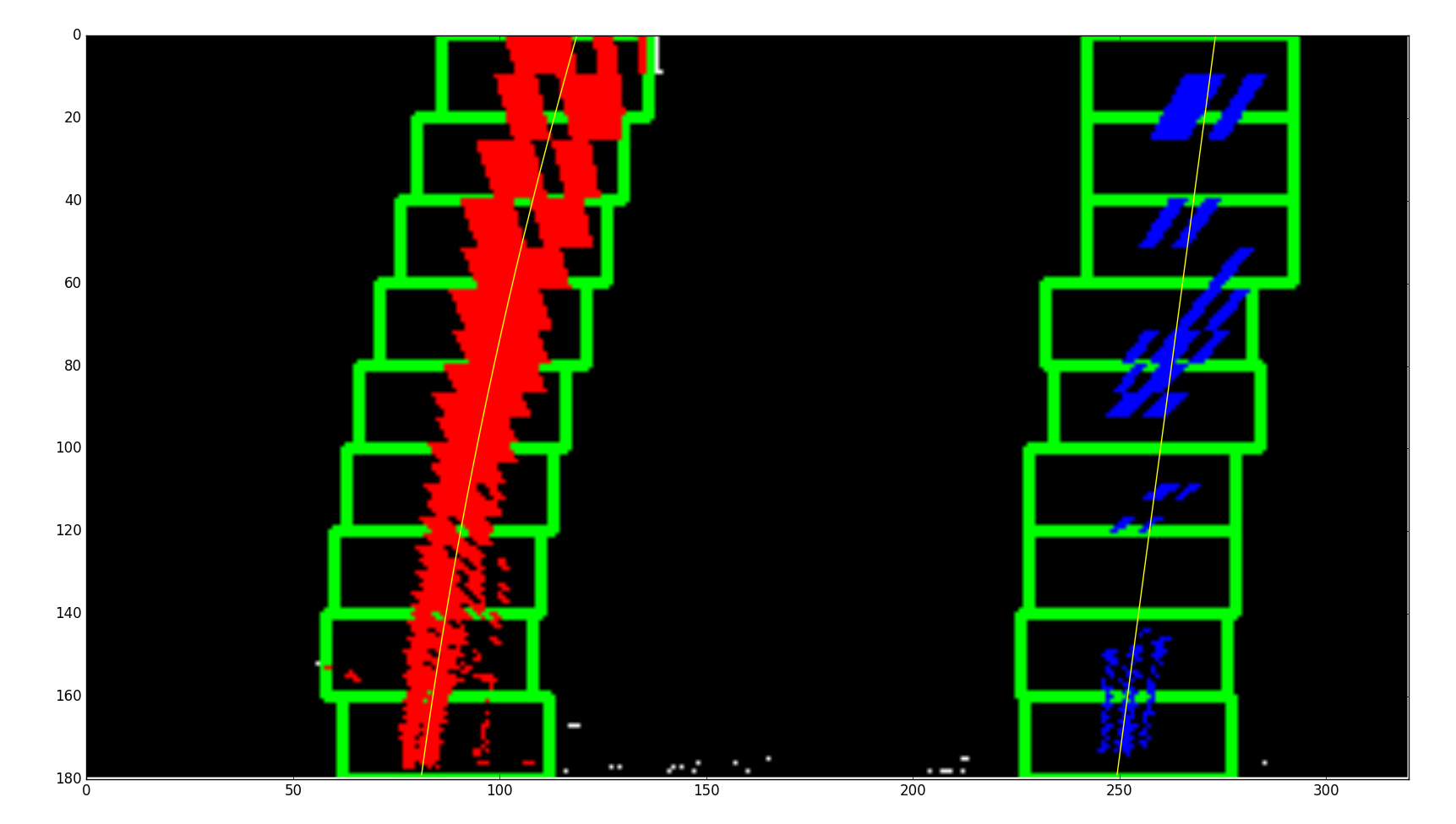
From that point, I use a sliding window, placed around the line centers, to find and follow the lines. It starts at the bottom, and search up to the top of the frame. The idea is visualized as the following figure.
-
Finally, I fit my lane lines with a 2nd order polynomial by
np.polyfitlike inlane.pyline 293:
For video
- If the input is video, the first frame can be treated the same as the individual image. Then we will have the estimated position of left and right lanes,
so it will be wise to take their positions as initiates for finding the lanes in the next frame. Therefore, a function named
trackerinlane.pyis used for this case. - In order to get smooth lanes among a sequence of frame, I use a frame buffer to save the lanes’ positions in previous N frame (line 25 in
lane.py). - If tracking fail (e.g. high standard deviation of the distance between left and right lanes), either keep previous lane positions or start a new detection.
5. Calculate the radius of curvature of the lane and the position of the vehicle with respect to center.
Radius of curvature
The radius of curvature of the curve at a particular point is defined as the radius of the approximating circle. You can see the reference here.
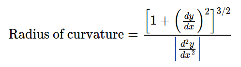
Function measure_lane_curvature in lane.py is implemented for this purpose.
Vehicle position
We assume the camera is mounted roughly at the center of the front window, and we have computed positions of the left and right lanes. So we could just take the bottom position of the left and right lanes, and compare with the middle of the image frame. Also, we could utilize the prior knowledge of the width of between left and right lanes (e.g. 3.7 m in US) to estimate the distance in real scale.
A function named off_center in lane.py is implemented for this purpose.
6. Lane augmentation and departure warning.
Finally, we could warp the detected lane region back to the original input frame. If the vehicle is driving too close to the lane edge, we could
warn the driver by changing the color from green to red (see function create_output_frame in lane.py).
Two video demos
1. Driving through shadows of trees
Video 1
2. Driving through confusing lanes areas
Video 2
Discussion
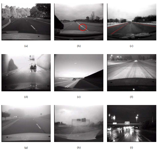
In order to be useful, driver assistance systems should reach very low error rates. For a warning system like LDW, the false alarm rate should be very low, as high rates irritate drivers and lead to system rejection. The exact amount of false alarms acceptable by drivers is still a subject for research [1]. Also, there are various of scenarios diversity which road and lane detection should cope with, and Lane and road appearance can change dramatically as the following figure.
Current implementation is purely based on monocular camera with computer vision techniques, it involves hard-code perspective transform and many manually tuned parameters for lane-line filtering. This maybe sufficient for good condition road driving, e.g. highway, daytime, clear lane marks, but it may fail with vairous of hard scenarios. In the future, we could consider two approaches:
- Use more sensing modalities other then only monocular camera when possible, e.g. Stereo camera, lidar, radar.
- Adopt machine learning techniques.
Reference: [1] Recent Progress in Road and Lane Detection - A survey